As a part of my freshman year advising seminar, 6.A01, I designed and fabricated fully-functional brushless DC motor from scratch. It featured wire-wound electromagnetic coils, an outrunner-style rotor with embedded permanent magnets, and a custom electronics panel that enabled four-phase control.
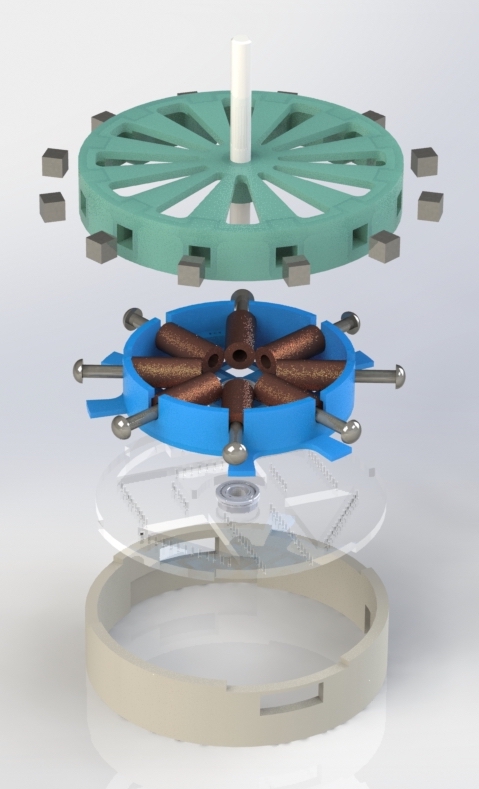
My motor design consisted of four components:
- Rotor: Contains 12 press-fit permanent magnets, mounted on a D-shaft
- Stator: Contains 8 drill-wound coils and two hall effect sensors for phase sensing
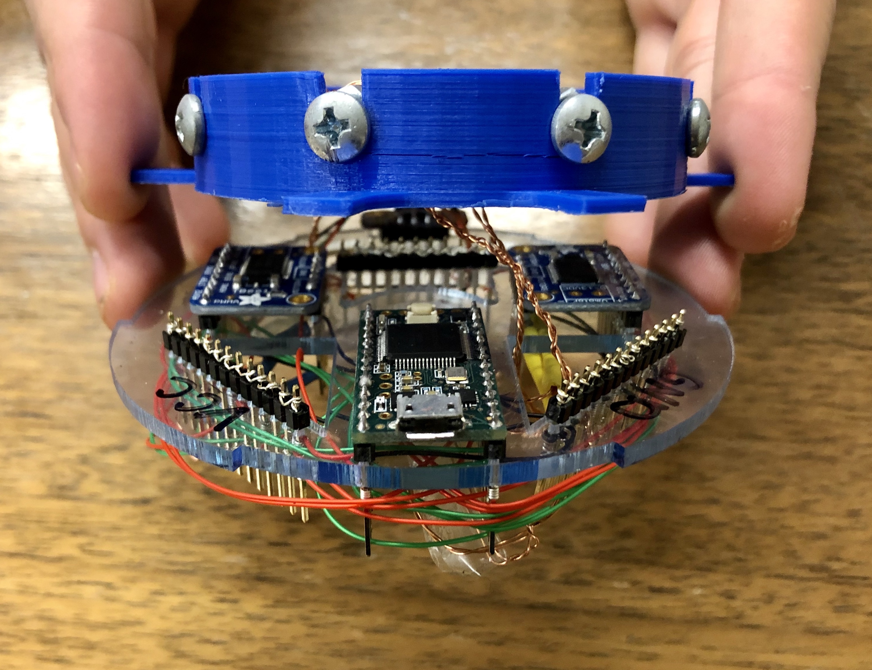
- Electronics Panel: Contains the Teensy, micro-USB breakout board, and two dual H-drives to control each electromagnet pair
- Base Case: The structural component that aligns the electronics panel and stator and stabilizes the rotor’s D-shaft

An exploded view of the motor's CAD, depicting (from top to bottom) the rotor, stator, electronics panel, and base case.
A video of my assembled motor running!

The stator portion of the motor. The inrunner design allows the coils are on the inside of the motor, allowing for more torque on the permanent magnet-including rotor.

The electronics panel of the motor. The Teensy, micro-USB power breakout board, and dual H-drive PCBs were all slotted into a custom-designed, laser-cut acrylic panel that allowed the electrical connections to be made via wire-wraps on the underside of the board.